A hard disk drive (HDD) is a data storage device that uses magnetic storage to store and retrieve digital data using one or more rigid platters coated with magnetic material. The platters are paired with magnetic heads, usually arranged on a moving actuator arm, which read and write data to the platter surfaces.
How is data stored on a hard drive?
Data is stored on a hard drive in a binary format, meaning 1s and 0s. These 1s and 0s are represented by the magnetization direction of small magnetic regions on the drive platters. A change in magnetization direction represents a 1 or 0 value.
The drive platters are made up of billions of these small magnetic regions, arranged in concentric, circular tracks. The tracks are further divided radially into smaller sections called sectors. Each sector stores a fixed amount of data, typically 512 bytes in modern hard drives.
As the platters rotate at high speed, the read/write heads float nanometers above them, allowing the heads to detect and manipulate the magnetization of the material passing beneath them. By changing the magnetic orientations of certain regions, data can be written. By detecting the magnetic orientations, data can be read.
How is data organized and accessed on a hard drive?
Data organization on a hard drive is handled by the drive’s firmware or sometimes an OS driver. This firmware organizes the surface of each platter into tracks and sectors. It also controls the movement of the actuator arm to position the heads over the desired track and sector.
When data is written or read, the firmware receives logical block addresses (LBAs) assigned by the OS. The firmware translates the LBA into a physical location – a specific platter, track, and sector. The heads can then access this precise area to read or write data.
The translation of LBAs to physical locations allows data to be dynamically managed and prevents applications from having to know the physical details of the drive. It also allows the drive to remap bad sectors.
How is data written to the platters?
To write data, the actuator arm positions the read/write heads over the desired track and sector. As the platter rotates beneath the head, the head generates a magnetic field modulated by the binary data, changing the magnetization of regions on the platter surface. This magnetic change persists after the platter rotates past the head.
More specifically, the head contains an electromagnet driven by an amplified current representing the 1s and 0s of data. A higher electric current aligns magnetic regions in one orientation, while a lower current or no current leaves the region magnetized in the original orientation. These magnetic transitions are later read to reconstruct the stored data.
The hard drive controller and firmware orchestrate the timing of signals sent to the head. They ensure the head writes to the desired location at precisely the right time as the platter spins.
How is data read from the platters?
Reading data is essentially the opposite process of writing. The actuator arm positions the head over the appropriate track and sector. As the platter rotates beneath the head, the magnetic orientations of the material induce voltages in the head coil.
The head and amplifier electronics detect the voltage levels, interpreting magnetic transitions as 1s and lack of transitions as 0s. The stream of 1s and 0s produces the original binary data written to the platter surface.
Precise timing circuits ensure the data is read from the correct platter location as it passes below the head. The process happens extremely fast, enabling hard drives to deliver data at high speeds.
How is the data buffered and transferred externally?
The hard drive has an integrated controller chip and temporary data buffers that assist in managing the flow of data during reads and writes. As data comes in from the heads, it gets processed through correction circuits before being temporarily held in a buffer.
When writing, an external source sends data to the buffer before it gets written to a platter. When reading, the buffered data gets sent out through the external interface. Buffering allows data to be collected and transmitted in efficient blocks rather than bit by bit.
Common hard drive interface protocols like SATA, SAS and FC have defined mechanisms for reliably sending and receiving buffered data blocks to and from a host computer or other device.
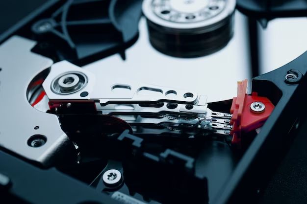
What is the basic anatomy of a modern hard drive?
A modern hard drive consists of several key components enclosed in a metal chassis:
- Platters – Circular disks made of non-magnetic material, such as aluminum alloy, glass, or ceramic, coated with a thin magnetic layer for data storage.
- Read/write heads – Tiny electromagnetic coils that read and write data to the platter surfaces.
- Head actuator – The mechanism that positions the heads over specific tracks and sectors on the platters.
- Spindle motor – Spins the platters at high speeds, up to 15,000 RPM in some drives.
- Control circuitry – Microprocessors and memory chips that process data and control drive activities.
- Firmware – Low-level software that handles drive operations like track seeks and error correction.
- Interface – Connects to a host computer through protocols like SATA, SAS or FC.
- Buffer – Temporary data storage, usually DRAM chips, to optimize data flow.
Hard drives also have other components like a power supply, circuit board, casing, and sometimes built-in cooling fans. These provide electricity, mechanically support components, and dissipate heat.
What is track-to-track seek time?
Track-to-track seek time refers to the time it takes for the head actuator to move from one track to an adjacent track on the platter. It defines the agility of the actuator and determines data access times for sequential read/write operations.
Seeks between non-adjacent tracks take longer than between adjacent tracks. To move across multiple tracks, the actuator accelerates, coasts, and decelerates. Thus, large seek distances have higher latency.
Track-to-track seek time is typically under 1 ms in modern hard drives. Seek time has continuously improved over the years as actuator mechanismsadvanced from stepper motors to voice coils to advanced two-stage actuators.
What is average seek time?
Average seek time indicates the typical time required for the head actuator to move to any random track location on the platter. It is larger than track-to-track seek time due to the extra time needed to move across multiple tracks.
To measure average seek time, many seek distances are tested – from adjacent tracks out to maximum track distances. The times are averaged. Average seek times today are generally below 10 ms.
Average seek time depends on the speed of the actuator mechanism, the number of tracks on the platter, and the spread of data on the drive. It can range from under 1 ms for adjacent tracks to 15+ ms for the furthest track distances in consumer HDDs.
What types of memory caches are used in hard drives?
There are two primary caches in a hard drive:
- Disk buffer – Also called read/write cache, this is high-speed volatile RAM that temporarily holds data during read and write operations between the platters and computer. It helps manage the differences in speed between the platters and interface.
- Controller cache – This is nonvolatile flash memory on the drive controller that stores frequently accessed data, metadata like file tables, and queued write data. It provides faster access to this common data.
In addition, the computer or RAID controller managing the hard drive will usually have its own read/write cache in RAM to further optimize throughput.
What is Native Command Queuing (NCQ)?
Native Command Queuing or NCQ is an optimization feature of SATA hard drives. It allows the drive to internally optimize the order of received read and write commands, rather than strictly processing them in the order received.
NCQ uses the internal drive cache to reorder and queue up commands so they can be completed with reducedSeek times between tracks. This increases throughput and efficiency, especially formulti-threaded workloads.
For example, if requests come in for data at opposite ends of the platter, NCQ will reorder them so the head can access the data in one pass rather than constantlyseeking across the full diameter. The host still sees the completed results in the original request order.
What is TLER / CCTL and how does it impact RAID performance?
TLER (time-limited error recovery) or CCTL (command completion time limit) refers to a setting that defines timeout limits for error recovery before reporting a failure to the OS. It was introduced to improve RAID reliability by reducing timeout problems.
In non-RAID use, TLER is usually disabled to allow drives to take all the time they need to try recovering data. This prevents unnecessary drive replacement.
In RAID, TLER is usually enabled with short timeouts. This prevents long RAID rebuild times due to drive errors. The array can simply flag the problematic drive as failed faster instead of waiting for data recovery.
What is RAID and what are some common implementations?
RAID (redundant array of independent disks) combines multiple hard drives together to improve performance, capacity, or reliability compared to a single drive.
Some common RAID implementations include:
- RAID 0 – Disk striping to enhance performance. No redundancy.
- RAID 1 – Disk mirroring for redundancy. Provides fault tolerance if a drive fails.
- RAID 5 – Disk striping with parity data distributedacross drives. Allows one drive failure without data loss.
- RAID 6 – Similar to RAID 5 but can withstand failure oftwo drives.
- RAID 10 – Disk striping combined with disk mirroring.Requires at least four drives.
What are the typical steps in the hard drive manufacturing process?
Hard drive manufacturing involves many complex processes, typically including:
- Platter substrates are manufactured from non-magnetic material like glass or metal.
- Thin magnetic films are deposited on the platter surfaces.
- Servo patterns are written on the media to define tracks and sectors.
- Platters are polished to create ultra-smooth surfaces.
- Completed platters are assembled with the heads and actuator arm.
- Head positioning systems are tested and calibrated.
- Components are assembled into the drive enclosure.
- Drive firmware is loaded and testing is performed.
- Drives are subjected to burn-in testing before shipment.
Cleanroom environments are used extensively to minimize contamination. State-of-the-art manufacturing toolsperform many steps with high precision and repeatability.
How are read/write heads produced and integrated with the media platters during manufacturing?
Read/write heads are produced through a microfabrication process with thin film deposition, photolithography, and etching to create tiny electromagnetic coils surrounded by an aerodynamic slider structure.
After fabrication, the heads are merged with the platters through complex, precision robotic assemblies in cleanrooms. The platters are placed on spindles and the heads are integrated onto actuator arms known as head gimbals or head stacks.
The spacing between the head and platter surface must be infinitesimally small to allow reading and writing. The head assembly provides gram-scale actuation forces to fly each head nanometers above its platter at high speeds.
How has hard drive technology evolved over time, leading to increased capacity and performance?
Major developments that have enabled hard drive evolution include:
- Sealed enclosures – Allowed drives to be removed from cleanrooms and used in end products.
- MR heads – Use magnetoresistive effects to read data much more densely.
- PRML – Advanced signal processing to interpret data from high-density platters.
- Giant magnetoresistive (GMR) heads – Provided huge density gains in the 1990s.
- PMR – Perpendicular recording for further density increases.
- Helium drives – Reduced turbulence and friction on head media.
- Shingled recording – Partially overlapping tracks for more tracks per inch.
- HAMR – Laser-assisted recording for densities up to 10 Tb/in2.
Densities have jumped from kilobits per square inch to terabits per square inch over the decades, a 100 million fold increase. Maximum capacities have grown from megabytes to tens of terabytes.
What are the main limitations to continued hard drive scaling and density improvements?
Key challenges to scaling hard drives to higher densities include:
- Physical limits of magnetic recording technology.
- Manufacturing precision and mechanical tolerances.
- Costs and technical difficulties of new technologies.
- Data integrity and bit error rates.
- Increased power consumption and heat with higher densities.
- Requirements for backwards compatibility.
New breakthroughs will be needed to continue density scaling, which may involve entirely new technologies like bit-patterned media, heat-assisted magnetic recording, microwave-assisted magnetic recording, or other techniques still in R&D phases.
How do solid state drives (SSDs) differ from hard disk drives (HDDs)?
Some key differences between SSDs and HDDs include:
| SSD | HDD | |
|---|---|---|
| Storage medium | NAND flash memory chips | Magnetic platters |
| Data access | Electronic, random access | Mechanical, sequential |
| Interface | SATA, SAS, NVMe, etc. | SATA, SAS, FC, etc. |
| Latency | Microseconds | Milliseconds |
| Max performance | MB/s – GB/s | 100+ MB/s |
| Reliability | Highly variable | Generally high |
| Price per GB | Higher | Lower |
Conclusion
In summary, hard disk drives use sophisticated electromagnetic and mechanical engineering to reliably store huge amounts of data at low cost. Advancements like MR heads, PRML, and PMR have enabled astounding capacity growth over many decades. While nearing fundamental physical limits, hard drives continue driving the big data world with terabyte-scale, high-performance storage.