A hard disk drive (HDD) is a data storage device that stores digital information using rotating magnetic disks, or platters. HDDs were first introduced by IBM in 1956 and have been the dominant form of data storage for computers for many decades.
The hard drive manufacturing process has evolved over the years as technology has advanced, but it still consists of several key steps. First, the individual components that make up a hard drive must be produced. These include the platters, read/write heads, head actuator, and printed circuit board. Next, these components are assembled in a clean room environment. The platters and heads are merged into a head-disk assembly, the actuators are attached, and the electronics are added to create a complete hard drive unit. Finally, firmware is loaded onto the drive and extensive testing is conducted to ensure quality and reliability.
Overall, manufacturing hard drives is an extremely complex process requiring advanced engineering, finely-tuned production capabilities, and rigorous quality control. In the following sections, we’ll take a deeper look into each stage of making these critical data storage devices.
Hard Drive Components
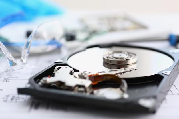
The primary components of a hard drive include magnets, platters, read/write heads, arms, motors, circuit boards, firmware, and casing (https://polaridad.es/en/materiales-del-disco-duro/). Hard drives store data on spinning disks called platters that are coated with magnetic material. The platters are spun by a spindle motor at speeds typically between 4,200 to 15,000 RPM. The data is written and read by the read/write heads, also known as heads or sliders. There are usually multiple platters stacked on top of each other in a hard drive, with one head on each surface for every platter. The heads float just above the platter surface on a layer of air as the platters spin. The heads are mounted on arms that can move the heads in unison across the platters to access different tracks. The movement of the arms is controlled by an actuator arm or actuator. A hard drive has electronic circuitry that controls the mechanical operation of the drive and interfaces with the host computer. Firmware provides the low level control for the drive and contains information like the drive’s model number and serial number. The internal components of a hard drive are enclosed in a metal chassis or casing to protect them from dust and interference.
Platter Manufacturing
Hard drive platters are the disks inside the hard drive that store data magnetically. Platters are made of either aluminum, glass, or ceramic substrates. Aluminum platters are often used in desktop hard drives, while laptop drives typically use glass platters due to their resistance to shock and vibration. Ceramic platters are also sometimes used.
To prepare the platter substrate for data storage, the surface is coated with a thin magnetic layer, usually 10-20 nanometers thick. This is done through a process like sputtering, where the coating material is physically transported onto the platter in a vacuum environment. Common coating materials include cobalt alloys and platinum alloys, which provide the magnetic properties needed to store data.
After the magnetic coating has been applied, the platters go through extensive testing and inspection. Parameters like surface finish, thickness uniformity, coercivity, and signal-to-noise ratio are measured to ensure the media meets specifications. Contaminant detection and glide testing are also conducted to check for any defects that could impact hard drive operation and reliability.
Head Manufacturing
The read/write heads in hard drives are manufactured using specialized microfabrication techniques like thin film deposition and photolithography to deposit and pattern the head materials at microscopic scale.
The process starts with a wafer of aluminum titanium carbide (AlTiC). Using a process called thin film deposition, layers of metals and insulating materials are deposited onto the wafer in nanometer thicknesses. Common materials include gold, nickel iron (NiFe), insulating alumina, and insulating diamond-like carbon (DLC). Each layer is patterned using photolithography, where light is shone through a photomask onto a light-sensitive photoresist coating on the wafer. This transfers the photomask pattern onto the wafer, allowing precise material removal and patterning.[1]
After the thin film layers are deposited and patterned, the wafer is lapped to achieve the desired head contour and thickness. The heads are then cut from the wafer using a dicing saw. At this point the heads are still rows of heads connected together, which get separated later on. The fabricated head rows then get assembled onto suspensions to form head gimbal assemblies (HGAs).
Head-Disk Assembly
The head-disk assembly brings together the read/write heads and hard drive platters to enable data access and storage on the disk. This is a delicate process that involves attaching the head gimbal assemblies to an actuator arm and positioning them precisely over the spinning platters.
The head gimbal assembly (HGA) consists of the read/write head mounted on a flexure that allows it to move and float on an air bearing above the disk surface. The slider containing the head is attached to the flexure using epoxy, with the electrical connections made using gold ball bonding or soldering (HDD head assembly).
The HGA flexures are then merged with the actuator arms and servo tracks to complete the head stack assembly (HSA). The HSAs are carefully positioned and aligned over the disk platters, with nanometer precision to ensure proper spacing and access to data tracks (Hard disk drive manufacturing process).
Great care is taken during the merge and alignment to prevent damage to the fragile slider heads. Cleanroom conditions are maintained throughout this assembly process.
Motor Assembly
The hard drive contains two motors – the spindle motor and the voice coil motor. The spindle motor rotates the disk platters at a high speed, typically 5,400 to 15,000 rpm. The spindle motor consists of a rotor and stator. The rotor contains a shaft that the disk platters are mounted on and an arrangement of permanent magnets. The stator contains electromagnets that generate a rotating magnetic field to spin the rotor and disk platters (HDD Spindle Motor). Manufacturers like MinebeaMitsumi use specialized precision bearings and drive control ICs to ensure stable rotation (MinebeaMitsumi).
The voice coil motor uses magnetic coils to quickly and precisely move the read/write heads across the platters. This allows the heads to access different tracks on the disk surfaces. The voice coil motor consists of an arm that holds the read/write heads, a voice coil, and magnets. Running current through the voice coil generates a magnetic field that interacts with the permanent magnets to move the head arm. The spindle motor and voice coil motor are assembled onto the hard drive baseplate.
PCBA Manufacturing
The printed circuit board assembly (PCBA) is where all the electronic components of the hard drive are assembled. It begins with the bare printed circuit board (PCB), which has the conductive pathways etched onto it. Components like the controller chip, memory chip, motor driver chip, and other supporting components are then soldered onto the PCB.
The soldering process is usually done by automated pick-and-place machines. These machines precisely place tiny electronic components onto their correct spots on the PCB, before solder paste is applied and the whole thing passes through a reflow oven to melt the solder and attach the components. For larger components like connectors, they may be soldered on manually.
Once everything is soldered onto the PCB, the fully assembled PCBA undergoes electrical testing and inspection. Automated testers are used to validate the functionality and performance of the PCBA based on its design specifications. Optical inspection systems also carefully examine the PCBA for any assembly defects or quality issues, like missing or misaligned components, poor solder joints, etc. Any boards that fail testing are reworked or discarded.
The result of the PCBA manufacturing process is a fully functional electronic board that provides the “brains” to control and operate the hard disk drive.
Firmware Loading
One of the final steps in manufacturing a hard drive is loading the firmware or control code onto the hard drive’s printed circuit board assembly (PCBA). The firmware contains the programming that allows the drive to communicate with the host computer and perform read/write operations (Seagate). This process involves writing the firmware code to the drive’s read-only memory (ROM) or flash memory chips on the PCBA via a specialized programming machine.
The firmware loading process differs slightly between hard drive manufacturers but generally involves connecting the hard drive to a jig or fixture that interfaces with the programming machine. The machine then transfers the firmware code to the drive’s memory chips. This allows the drive electronics to initialize, communicate via disk protocols like SATA or SAS, and control the positioning of the read/write heads (Reddit).
Loading the firmware is a delicate process that takes several minutes to complete. The machine carefully checks the code was written correctly via checksums or other verification methods. Once firmware loading completes, the drive can be disconnected and prepared for final assembly and testing.
Final Assembly
The final assembly stage brings together all of the components manufactured earlier in the hard drive production process and assembles them into a complete storage device. This stage requires meticulous care and precision to ensure proper alignment and connection of the delicate components.
First, the base plate is prepared. This metal plate forms the bottom cover of the hard drive and holds the spindle motor in place. The spindle motor is mounted onto the base plate using fasteners or adhesives.
Next, the head disk assembly (HDA) is lowered carefully onto the base plate and spindle motor. The HDA contains the platter, heads, and head actuator assembled previously. It rests on top of the spindle motor so that the motor can spin the platter.
Now the fragile head-platter unit must be connected to the controller board (PCBA). The actuator arm inside the HDA has an exposed flexible circuit cable. This flex cable is meticulously connected to the appropriate pins on the PCBA using automated machines or manual labor.
With all components mechanically assembled, the final cover is lowered over the HDA and screwed into the base plate. This fully encloses the internal parts within a protective metal casing.(Chu)
The hard drive has now been transformed from a collection of components into a functional data storage device. It is nearly ready for deployment after final testing and quality checks.
Testing and Quality Control
Once assembly is complete, each hard drive goes through rigorous testing to ensure quality and reliability. Every component and function is tested, including read/write heads, spindle rotation speed, shock resistance, power consumption, and data integrity.
Hard drives are stress tested by subjecting them to extreme temperatures, vibration, and drops. Tests are run continuously for 48-72 hours to validate consistent performance over time. According to Advantech, automated testing systems from suppliers like Axus Technology and Giga-Byte Industries are commonly used for reliability and durability testing at high volumes (Advantech, 2009).
Precise lasers, sensors, and imaging systems verify sub-micron measurements and positioning of components. Any drives that fail testing are diagnosed and repaired if possible. If not, the components are recycled. Only drives that pass all functional and performance criteria are approved for shipment.
By thoroughly exercising all functions and ensuring specifications are met, quality control testing delivers reliable, high-performance hard disk drives.