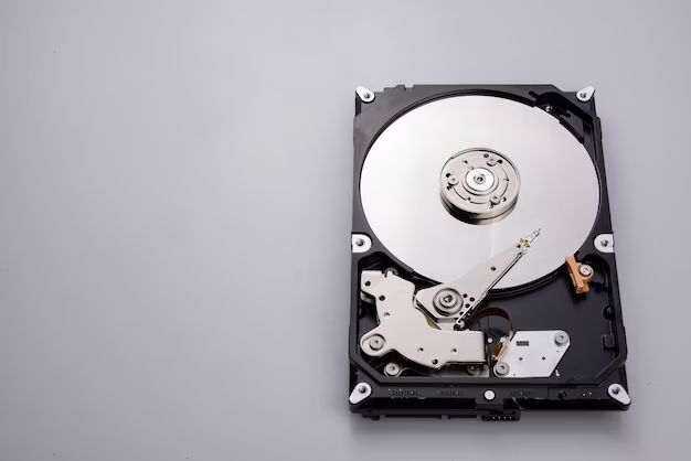
A hard disk drive (HDD) is a data storage device used in computers and other devices. It contains rotating magnetic disks called platters that store data, with read/write heads that move across the platters to access the data. There are three major components that make up a hard disk drive system:
1. Platters
The platters are the circular disks inside the HDD that actually store the data. They are made of non-magnetic material, usually aluminum alloy or glass, and are coated on both sides with a thin layer of magnetic material. Typically an HDD will have several platters stacked on top of each other in the drive.
Data is recorded on the magnetic coating of each platter surface in concentric tracks. The presence or absence of magnetization in a spot represents binary data – a 1 or a 0. As the platters spin at high speeds, the read/write heads float just above the surface on a thin cushion of air, accessing data as needed.
Having multiple platters adds to the total data storage capacity of the HDD. More platters with more usable data surfaces allow more data to be stored in the same footprint. Platters have continued to become smaller, thinner and more densely packed to achieve greater and greater data capacities in the same HDD sizes over time.
2. Read/Write Head
The read/write heads are the components that actually read and write data to and from the platters by magnetizing and sensing the magnetization of the platter surfaces.
A read/write head is affixed to the end of an actuator arm in the HDD. There is one head per platter surface. The arm rapidly moves the head across the radius of the platter as it spins, allowing the head to access data from multiple tracks across the full surface area.
The head contains an electromagnet that generates magnetic fields to orient magnetization on the platter surface when writing data. It also contains a sensor that detects the magnetic fields from the surface to read back the stored data.
Heads float nanometers above the platter surface. They are designed to be as small and lightweight as possible to allow fast access across the platters while maintaining the delicate head-platter spacing. As storage densities have increased, read/write heads have evolved from ferrite to thin-film inductive and magnetoresistive (MR) designs.
3. Actuator
The actuator provides the rapid and precise movements to position the read/write heads on the desired tracks across the platters. It consists of an actuator arm that holds the head, a pivot bearing, a voice coil and motor.
The actuator arm extends like a radius from the central pivot point out over the stack of platters. One head is mounted on the end of each arm, allowing it to reach the surface of every platter from the single arm.
The pivot bearing provides smooth and accurate rotational motion for the actuator arm as it sweeps from the inner to outer tracks of the platters. A common bearing design is a dual ball bearing pair separated by spacer washers.
The voice coil and motor work together to rapidly rotate the actuator to move the heads across the platters during drive operations. The voice coil is a magnet surrounded by wire coils. Running current through the coils generates torque to turn the actuator arm due to magnetic interactions. A servo control system provides the current and direction to precisely position the heads.
Detailed Explanations
Now that we have an overview of the three core HDD components, let’s look at each in more depth:
Platters
Platters are the disks that provide the actual data storage surface area in hard drives. Some key details about HDD platters include:
– Made of non-magnetic material – usually aluminum alloy or glass for rigidity and coated in a thin magnetic layer. Provides a rigid base while allowing the magnetic coating to define the data storage.
– Store data on both top and bottom surfaces. Platters are double sided to maximize storage capacity.
– Stacked on a central spindle in the HDD. Multiple platters are stacked to multiply total data capacity. Spindle provides alignment and high speed rotation.
– Data is laid out in concentric tracks on the platter surfaces. Billions of tracks providing billions of bits of capacity. Tracks are divided into data sectors.
– Platters spin at high speeds, typically 5400 to 15,000 RPM during operation. Faster spin rates allow data to move under the heads faster.
– Trends are for smaller 3.5″ and 2.5″ platters over time, allowing smaller drives. Also thinner platters to pack more into the same vertical space.
– Higher areal density – tracks and bits per inch continuously increasing. Allowing more data capacity in the same platter area through technology evolution. 500 Gb/in2 typical today.
Read/Write Heads
The read/write heads are petite electromagnetic transducers that are able to interpret and modify the magnetization of platter surface domains to read and write the data. Key characteristics include:
– Usually one head per platter surface, all connected to a common actuator arm so they move in unison.
– Use an electromagnet integrated with a detection sensor for writing and reading data.
– Writing is achieved by modulating magnetic fields from the electromagnet to orient magnetization of domains.
– Reading is achieved by sensing the magnetic field emanating from the domains with the magnetoresistive sensor.
– Components are encapsulated in a slider coupled to the actuator arm. Slider provides aerodynamic lift profile for head-platter spacing.
– Very lightweight and compact – tenths of a gram. Enables fast positioning and minuscule head flying height.
– Touchdown zones on platter allow heads to land when not operating. Heads fly on air bearings over data areas.
– Originally ferrite heads – now evolved to thin-film inductive write and MR or GMR sensor reads.
– Continuously decreasing size to increase data density by allowing narrower tracks and reduced flying height.
Actuator Assembly
The actuator assembly contains the electromechanical components that swing the arm and fine tune the head position radially across the platters. Details include:
– Holds all the heads together on a single structure. Allows multiple platters to be accessed simultaneously.
– Rotates about a central pivot bearing. Provides smooth low-friction rotation for precise control.
– Actuator arm extends heads out over platters like a radius. Sweeps full radius for track seeking.
– Voice coil motor rapidly accelerates arm for fast seeks. Allows 10-50+ seeks per second.
– Servo control system positions arm/heads accurately. Closed loop control fires voice coil as needed.
– Must be balanced – equal mass on both sides of pivot point. Prevents arm from being pulled off-center.
– Some use ball bearings, others rotate on journal bearings for less friction.
– Magnets may be on the arms or housing depending on design. Interact with moving voice coil.
– Compact and rigid materials used – stainless steel, aluminum alloys. Provides resonance protection.
How the Components Work Together
Now that we’ve covered each of the three core pieces individually, it’s important to understand how they interact and operate together to read/write data:
Reading Data
The reading process works like this:
1. The actuator arm positions a read head precisely over the correct track on the spinning platter surface. This is done by moving the whole assembly including arm, pivot and voice coil motor.
2. As the track spins under the head, the magnetic domains on the platter surface produce magnetic field fluctuations. These minute fields induce voltage changes in the MR sensing element in the head.
3. These voltage signals correspond to the binary 1’s and 0’s of the data, allowing the head to interpret the data encoded on the platter surface.
4. Precision alignment and nanoscale head-platter spacing allows the head to distinguish very closely spaced magnetic domains on the platter, reading back data at high densities.
5. The head electronics amplify and decode the signals into data that is passed back to the drive interfaces and host system.
Writing Data
Writing data involves this process:
1. The actuator arm positions the write head precisely over the target track for recording the new data.
2. Currents are applied to coils in the head to produce magnetic fields from the write electromagnet. Direction and intensity are varied based on the input data.
3. These fields magnetize tiny domains on the spinning platter surface under the write head. Domain magnetization directions mimic the input binary data.
4. Write currents switch on and off very quickly, modifying domains in real time as new data comes in. This is buffered to optimize densities and disk performance.
5. Precise head positioning and minute magnetic fields produced allow very high data densities to be written to the platter surfaces.
6. The servo control system ensures the heads stay centered on the data tracks during writing for data integrity.
Head Technology Evolution
The read/write heads are central to HDD evolution and growth in storage capacities over time. Head technologies have progressively advanced to read from and write to smaller and smaller magnetic domains on the platter surfaces. Some major milestones include:
Ferrite Heads
– The original head technology used a ferrite core for the electromagnet. A small coil wrapped around the ferrite generated fields for writing.
– Early read elements were also ferrite based, sensing fields passively via magnetic induction.
– Ferrite heads were bulky and only able to read wide, sparse tracks and domains. Storage density was very low as a result.
Thin-film Inductive Heads
– Started replacing ferrite heads in the 1980’s, marking a huge density jump.
– Used thin-film deposition tocreate very compact copper write coil around an alloy or ferrite core.
– Writes are induced in media via sharper magnetic fields from smaller write gap.
– Still used a ferrite sensing element to read – limited to wide tracks.
Giant Magnetoresistive (GMR) Heads
– Introduced the magnetoresistive sensor to boost reading resolution.
– GMR sensor changes resistance sharply in low magnetic fields from domains.
– Allows detecting much smaller bit lengths along tracks by directly sensing fields.
– Enables reads from far narrower tracks and domains on platters.
Tunneling Magnetoresistive (TMR) Heads
– Further MR sensor refinement for even stronger signal outputs.
– Uses quantum tunneling effects across ultra-thin insulating layers.
– Allows drive densities of over 100 Gb/in2.
– Other advanced MR technologies continue to be developed.
– Writing still done with thin-film inductive elements.
Conclusion
In summary, hard disk drives rely on platters, read/write heads, and actuators working together to provide high-capacity digital storage:
– Platters supply the smooth, rigid magnetic recording surfaces to define bits via magnetization changes.
– Read/write heads employ advanced electromagnetic and magnetoresistive effects to detect and modify magnetization.
– Actuators leverage voice coils and servo control systems to position heads precisely and rapidly.
– Together these components have enabled the incredible growth in HDD capacities over the decades.
Ongoing improvements across all three areas will push capacities even higher in the future through further density increases. Engineers continue to refine and introduce new techniques in areas like head technology, platter materials and bit patterning, actuator designs, and control algorithms to pack more data into smaller hard drives.