What is a Hard Drive?
A hard drive, also known as a hard disk drive (HDD), is a data storage device that stores and retrieves digital data using spinning platters coated with magnetic material (Source: https://www.techtarget.com/searchstorage/definition/hard-disk-drive). Hard drives are one of the main components inside computers and are responsible for permanently storing data.
The main components that make up a hard drive include (Source: https://smallbusiness.chron.com/four-major-components-hard-drive-70821.html):
- Platters – The disks that actually hold the data. They are made of non-magnetic material like aluminum or glass and are coated on both sides with a thin layer of magnetic material.
- Read/Write Heads – Devices that read and write data to the platters. There is one head for each platter surface.
- Spindle – The axis that spins the platters at very high speeds.
- Actuator Arm – Moves the heads to the proper track on the platters for reading or writing data.
Data is stored on the magnetic surface of the platters in concentric tracks. As the platters rotate at high speed, the actuator arm moves the heads over the surface of the platters to read or write data. Hard drives use magnetism to create and detect the presence or absence of 1’s and 0’s to store data. By magnetizing a tiny spot on a platter to represent a 1 or leaving the spot demagnetized to represent a 0, hard drives are able to store large amounts of digital data.
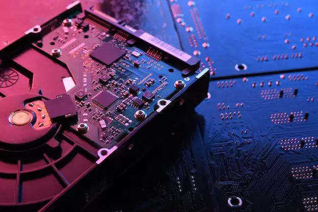
The Printed Circuit Board (PCB)
The printed circuit board (PCB), also known as the logic board or controller board, is the main circuit board located on the underside of a hard disk drive. It houses the drive’s main electronic components and serves several key functions:
The PCB controls the motion of the drive’s spindle motor, which rotates the platters, and the actuator arm, which positions the read/write heads over specific tracks on the platters. It provides the processing capabilities to translate logical block addresses into physical locations on the disk and route data to and from the platters through the read/write heads [1].
The PCB also contains a microcontroller chip that runs the drive’s firmware, which provides the intelligence to manage drive operations. In addition, it has a preamplifier to boost and condition the very weak electrical signals coming from the read/write heads before sending them to the host computer [2].
Other key components on the PCB include RAM cache to improve performance, connectors for the data and power cables, and sometimes an Ethernet port or serial port for monitoring purposes.
Firmware and Controller Chip
The firmware is the operating system that gives the hard drive its basic functionality, allowing it to read and write data properly. It contains the program code that controls the drive’s operations like positioning the read/write heads, spinning up the disk platters, and caching data [1]. Firmware is stored on a small memory chip as well as on reserved areas of the hard disk platters. The firmware acts as the hard drive’s “brain” by initializing it, managing its performance, and assisting with diagnostics.
Every hard drive also contains a controller chip that allows it to communicate with the host computer via the interface protocol. Common interface protocols include SATA, SAS, and NVMe. The controller chip translates the computer’s requests into instructions for the drive hardware. It contains the logic to locate, access, and transfer data as needed. The controller chip essentially facilitates the two-way communication between the disk drive and computer [2].
Preamplifier
One important component on the hard drive is the preamplifier, which is a small chip located near the read/write heads. As described by Aesonlabs, “The preamp amplifies the signal sent from the heads to the PCB. Without a preamp, the hard drive would be much like a record player, without amplification” (https://aesonlabs.ca/blogs/what-is-inside-a-hard-drive-complete-stripdown/). The preamplifier strengthens the signal between the read/write heads and the PCB, allowing the data to be transmitted reliably across the internal components.
According to HDDscan, “The preamp is a chip, that controls heads and amplifies signals from/to them” (https://hddscan.com/doc/HDD_from_inside.html). Without the preamplification, the signal from the heads would be too weak for the PCB to interpret accurately. The preamp boosts the signal to an appropriate level before passing it to the controller electronics.
Overall, the preamplifier plays a crucial role in enabling the hard drive heads and PCB to communicate effectively. By strengthening the signal, it allows the data read and written by the heads to be transmitted reliably to the circuit board for processing.
Read/Write Heads
The read/write heads are the small components inside a hard drive that read and write data onto the magnetic platters (Techopedia, 2022). Each platter surface has a corresponding read/write head that works in tandem with it. The heads float just above the rapidly spinning platter surface on an air bearing and use electromagnets to read and write data (Wikipedia, 2022).
As the platters spin, the heads detect and produce electromagnetic fields to encode binary 1s and 0s onto specific points on the platter. On a read operation, the heads detect fluctuations in the magnetic fields of the platters to decode the binary information. Modern hard drives often have multiple platters stacked on top of each other, with 2 heads per platter – one for the top and one for the bottom surface. So for example, a hard drive with 3 platters would require 6 separate read/write heads (Techopedia, 2022).
The heads are a critical component that transforms the hard drive’s physical storage into usable digital memory. Careful engineering goes into their aerodynamic design and electromagnetic operation to maximize data access speed, density, and reliability.
Motors
Hard drives contain two important motors: the spindle motor and the actuator arm motor. The spindle motor rotates the magnetic platters at a high speed, typically between 5,400 and 15,000 rpm. The actuator arm motor moves the read/write heads back and forth rapidly across the surfaces of the platters to access data. As described in this article, these brushless DC motors contain multiple sets of coils that are precisely controlled by the drive’s firmware and circuits:
https://www.justanswer.com/electronics/1sfwd-old-hard-drive-phase-brushless-motor-3-wires.html
The spindle motor needs to spin smoothly and consistently to enable accurate positioning of the heads over the data tracks. Any vibration or fluctuation in speed can interfere with data reads and writes. The actuator arm motor also requires finely controlled movement to quickly and precisely move the heads across the platters without crashing into them. Both motors work together closely to access and read/write the drive’s data.
Connectors
The printed circuit board (PCB) contains connectors that allow it to interface with the rest of the computer system. The two main types of connectors found on a hard drive PCB are:
Data Connectors
Data connectors allow data to be transferred between the hard drive and the computer. Modern hard drives mainly use SATA connectors, while older drives used PATA/IDE connectors.
SATA connectors are narrow data cables with locking connectors that provide high speed serial data transfer. PATA connectors use wider cables and parallel data transfer.
Power Connectors
Power connectors provide electricity to run the components on the PCB. Hard drives are typically powered by either a 4-pin Molex connector or a 15-pin SATA power connector.
The PCB routes power from these connectors to key components like the spindle motor, actuator arm, and on-board cache. Proper power must be supplied for the PCB to function.
Cache
Hard drives contain a small amount of memory called cache that acts as a buffer between the drive’s main components and the computer’s main memory (RAM). The cache stores frequently accessed data for quicker retrieval, helping to speed up the overall performance of the hard drive.1
There are generally two types of hard drive cache – read cache and write cache:1
Read cache holds data most frequently requested by the system, allowing the hard drive to access this data faster than if it had to locate it on the drive platters. Write cache is used as a buffer when writing data to the disk, allowing the system to write to the cache and have the drive write to disk later.
Larger cache sizes generally provide better performance. Many modern hard drives have cache sizes from 8MB to 256MB. Solid state hybrid drives (SSHDs) may have up to 8GB of flash memory acting as cache.
Troubleshooting a Faulty PCB
The printed circuit board (PCB) is one of the most fragile components of a hard drive. If it gets damaged, the hard drive will not function properly. Symptoms of a faulty PCB include the hard drive not being detected by the computer, not spinning up, or making clicking or beeping noises.
There are a few steps you can take to troubleshoot a potentially faulty PCB:
- Visually inspect the PCB for any damaged components or burnt areas.
- Check the firmware chip to ensure the contacts are not corroded.
- Test the drive with a donor PCB to isolate the issue.
- Measure voltages coming from the PCB using a multimeter.
If the PCB is confirmed to be defective, you have two options:
- Attempt to repair the existing PCB by replacing damaged components.
- Swap in a replacement PCB. This typically provides the best results, but finding an exact match PCB can be difficult and expensive.
PCB replacement guides like the one found on DonorDrives.com provide step-by-step instructions for safely swapping the PCB on most hard drive models.
Conclusion
A hard drive’s printed circuit board is a crucial component that allows the various parts of the drive to function together. The PCB houses the controller chip, which acts as the brain of the hard drive, coordinating all read/write operations. It also contains the preamplifier, which boosts and regulates the signal between the read/write heads and the controller chip. Other key parts of the PCB include the connectors, which allow the drive to interface with the rest of the computer, and firmware, which contains the hard drive’s basic operating instructions.
Without a properly functioning PCB, the hard drive would not be able to perform basic operations like spinning up, seeking data, or reading/writing data. Issues with the PCB can prevent a hard drive from being recognized by the computer entirely. Given the vital role of the printed circuit board, a damaged or malfunctioning PCB is one of the most common reasons for hard drive failure. Understanding the purpose and function of the PCB is key for troubleshooting hard drive issues.
